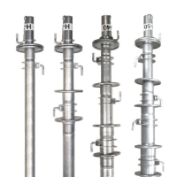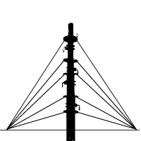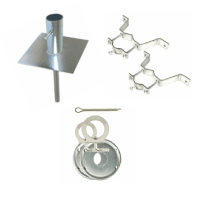
Remember those older AM/FM Portable Radios with the antenna that you extended by pulling it out? Or the Radio Antennas on older cars that would pop-out, extend and retract when you turned on the radio? This Mast isn't an Antenna in and of itself, but it extends and retracts by hand in similar fashion. Available in 20', 30', 40' and 50' heights. All ROHN telescoping masts are pre-galvanized and come assembled with mast hardware. Erection is made by simply connecting guys and brackets to the attached unique heavy duty rolled edge guy rings and clamps, extend each section one at a time (starting with the innermost section), insert the locking cotter pins, rotating the tubes to a locked position, and tightening the clamps. Repeat the process on each successive section until fully erect.
The unique ROHN Products design features interior tube flanging combined with a double crimped exterior tube to produce a stronger and more stable joint than most common masts. This design exclusive also prevents the sections from accidentally pulling apart and allows disassembly by pulling each section out through the lower end.
Each section extends deeper in to the lower tubes than most other designs, adding still further to the stability of the structure.
H Series
This heavy duty series uses 1-1/4" 16 gauge galvanized tubing for top section. All other sections are 18 gauge.
Assembly (2 Man Team min., no Wind)
1. Pre-install Mast Base with its Anchor Pin embedded into a small concrete Pad (mindful of frost layer depth) that extends its height above surrounding Grade Level (finished surface should have an ever so slight Crown as to prevent Water Pooling.
Install the Down Guy Earth Anchors into firm soil, clay or embedded concrete with a depth that allows only a few inches of the anchor rod and the anchor head showing above Grade.
(see the installation Guide/ Spec. Sheet and/or Associated Graphs/Photos for particular Mast Sizes for distances, angles and guy wire lengths)
2. Secure guy wires of the proper length needed to reach the anchors to the Guy Ring at the top of the Bottom Outermost Mast Section, through the appropriate Hole provided on the Guy Ring (holes for 3 and 4 way guys) and then back on the wire itself, terminating said guy wires with 3 Cable Clamps in a Row
3. Mount entire collapsed Telescopic Mast onto Base as provided, and attach the other end of the guy wires you just terminated onto the Down Guy Earth Anchors. Align the mast vertically while tensioning the Guy Wires to maintain plumb under tension.
4. Next, select the Top Innermost Mast Section (1.25" 16 gauge) and Secure its upper Guy Ring using the provided Mast Clamp to the desired location height anywhere along this particular Mast Section upon which it will rest securely under tension(see note 8 on page 10). The Guy Ring on this Mast Section only, can be affixed anywhere along the length of the Mast to leave room for Antenna Structure Attachments, Appurtenances etc., above it. (none of the remaining Mast Sections will have this adjustment Feature)
5. Secure (Terminate with 3 Cable Clamps in a Row) the appropriate length Guy Wires to this previously affixed Guy Ring and let them hang freely out of the way until all sections are raised.
6. Locate the Cotter Pin Holes at the top of the next innermost nested Mast Section and view while raising the previous Mast Section until you see its Bottom pass above the Cotter Pin Holes.
(At this point the Mast Section is extended Completely)
7. Insert a cotter pin passing through the Holes, secure and then lower the raised Section as to Rest upon it.
(There are usually half circle notches at the Mast bottom that will "saddle" the Cotter Pin when lined up)
Assure the Proper Installment of the Cotter Pin, the Mast's Position resting upon it and then tighten the mast clamp.
(the cotter pin remains for security and failsafe)
8. Secure appropriate length guy wires to the next highest Guy Ring of the corresponding Mast Section, and let them hang.
9. Raise the next smallest Mast Tube and insert the cotter pin.
210. Make sure that the cotter pin is inside/below the notch appearing at the bottom in the inside tube.
11. Secure the cotter pin and tighten the mast clamp.
12. Repeat steps 8-10 until all sections have been raised and are secured.
13. Attach all hanging Guy Lines to their respective anchor. Align the mast vertically by tightening the Guy Lines. Make sure to work your way up the mast while tightening.
![]()
This Buyers Guide has will answer many questions you may have on this Product Line. For more detailed information and Specification Sheets covering many aspects of Various Parts, Accessories and Installation Scenarios... Please refer to the "Telescopic Mast" Link above !!!
Telescoping Masts are not recommended for commercial, CB or beam antenna installations.
Antenna load (top load) should not exceed an effective projected area (EPA) of 2 square feet (see your antenna specifications).


